[fixed] TM1637 LED display “not working”.

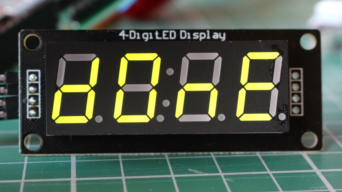
Last week I got 2 of these displays from a friend who couldn’t get them to display anything. (He knows I like those challenges.) Below picture proves it now works.
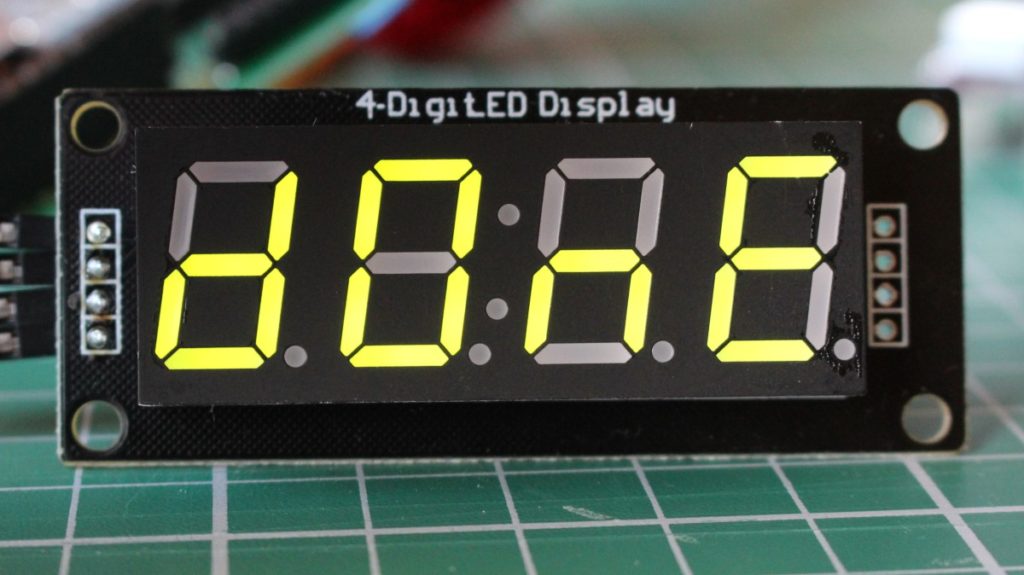
What was the case:

The data sheet says (e.g. in the schematic at page 8) a 100pF capacitor should be placed on CLK and DIO lines to GND.

verbatim quote from the data sheet: “100pF capacitor connected to the DIO, CLK communication port pull-up and pull-down can reduce interference to radio communications port.”

The capacitor is probably meant to reduce the signals rise time and thus reduce high frequency harmonics.

On the PCB, a 10nF capacitor was present, and that’s the cause of the display not functioning, just like overly long connections would cause this (when the wire length itself adds to much capacitance)

So, for those of you who bought one of these displays on Aliexpress, DX, or ebay, try removing those 2 capacitors (Or replacing them with 100 pF) if the display doesn’t work.
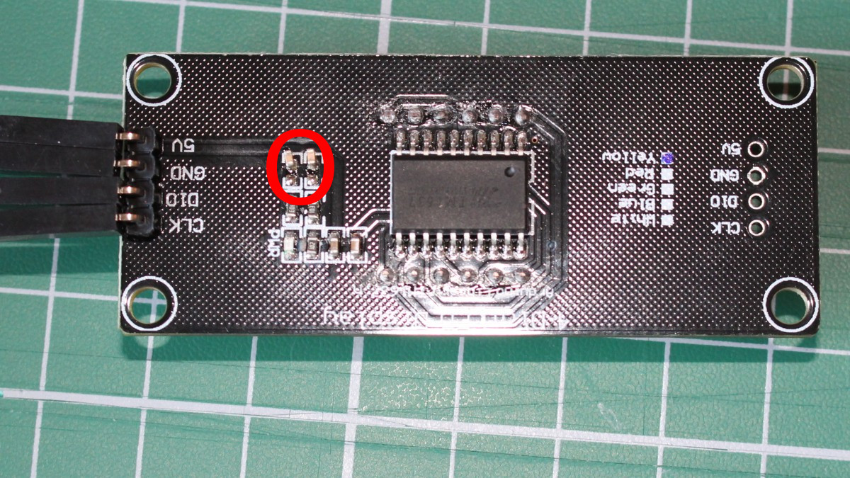
lowres_tm1637_desolderCsOnDioAndClk_circled
remove those 2 capacitors or replace them with 100 pF

Tags:

Comments

3 responses to “[fixed] TM1637 LED display “not working”.”

  1. Ed Hayes Avatar

    Thank you! That solved my problem! Mine had 1uf capacitors on those lines. LOL. What were they thinking?

  2. Mark Avatar
    Mark

    Hi.

    I have a TM1637 that works intermittently, after a few minutes of correct function it will just freeze on whatever data was on display at that time. My troubleshooting took me to the datasheet which spoke about capacitors, and a google search then brought me here.

    How can I tell what the components soldered to the back of the wee board are? They are far too small to see any detail. How did you know that the capacitor on yours was 10nF?

    1. Lucas Avatar
      Lucas

      I desoldered and measured them.

      But considering your display works for a while before freezing, I doubt it’s those capacitors: if the signal risetime was too slow (what a too large capacitance on the bus causes) i’d expect the display not to work at all.

      I don’t remember whether I measured risetime of the lines first before desoldering the capacitors…

      Is the risetime fast enough? Does another display work if you sent the same data to it / does a logic analyser display correct data / is the software controlling it known to work correctly?

Leave a Reply

Your email address will not be published. Required fields are marked *